I’m Andrew and I like weird little projects. I built a weird little FitBit walking robot. I built a weird little cyborg see turtle. I built a weird little face-mounted Lidar array that lets you see the world like a dolphin. I built a weird little ring light with a panic button to get you out of annoying zoom calls.
I’ve also written a few guides on how you, too, can make weird little projects with your kids.
I also make not-so-weird, not-so-little conservation technology projects aimed at making to tools of ocean science accessible to those most directly impacted by our changing oceans.
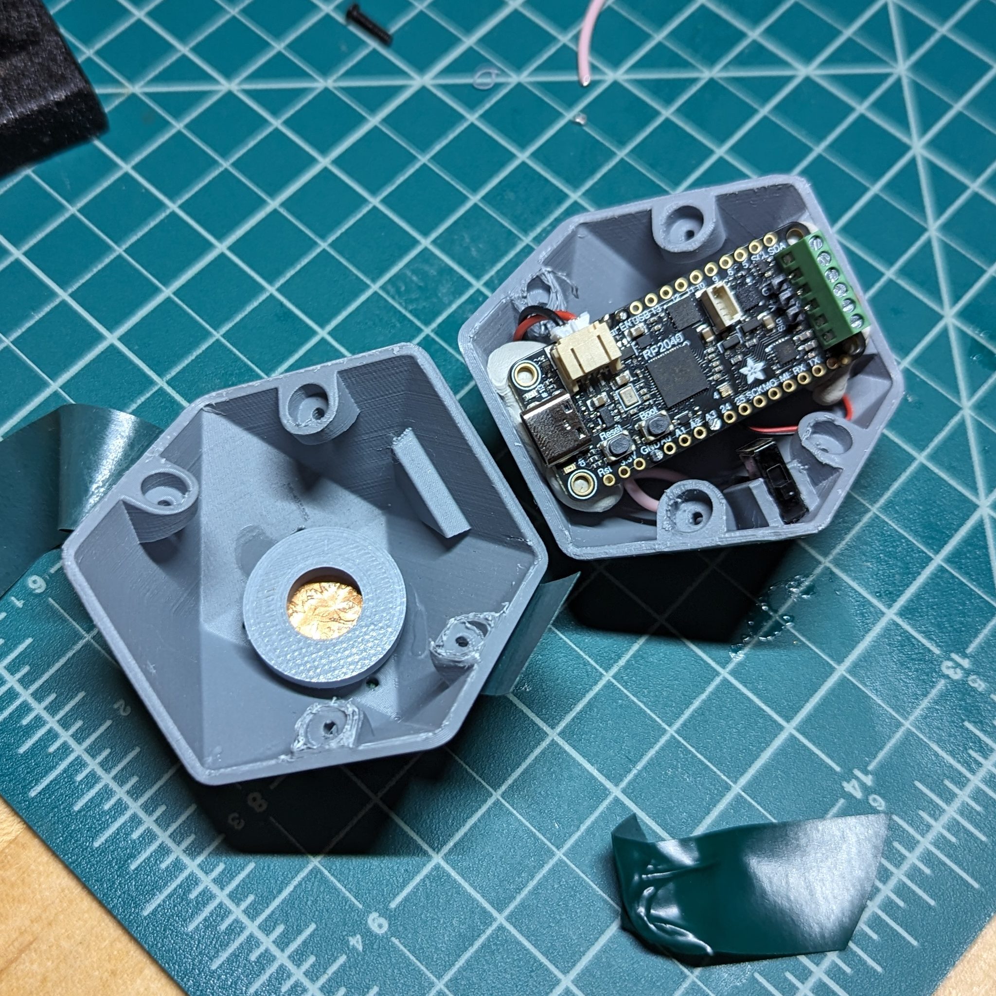
This weekend, I sat down with my kiddo to make another weird little project, this talking D20 that announces what you roll when you roll it and laughs at you for making a bad roll.

A 3d-printed talking D20 that knows its own orientation is the platonic ideal of a weird little project.
But something interesting happened while working on this weird little project. The kiddo did something clever with power management.
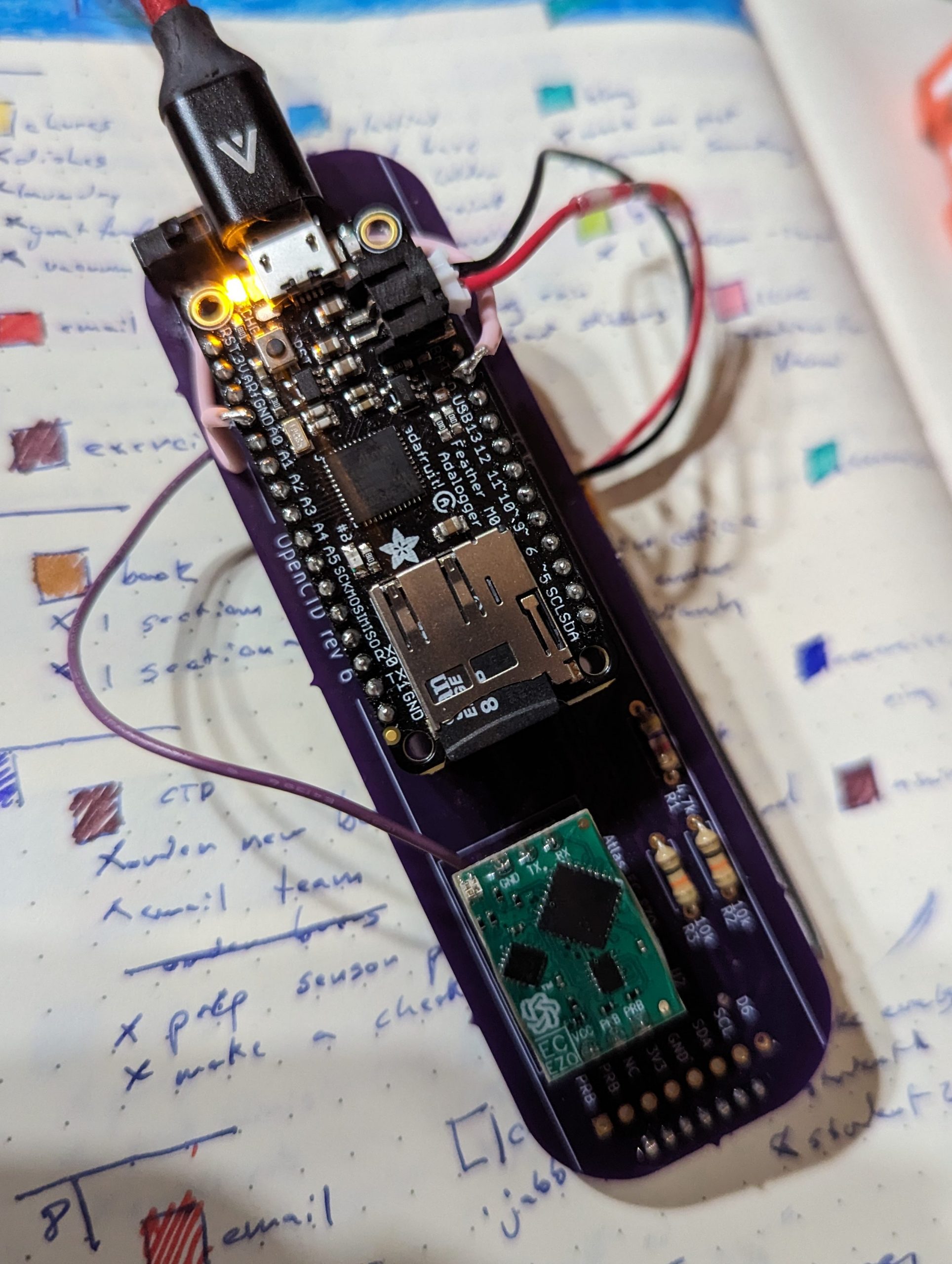
The OpenCTD has a few annoying quirks, legacies of how it was developed and of our commitment to using low-cost, easily sourced parts. The power supply is connected to the OpenCTD directly through an electromechanical switch. Turning off the OpenCTD means the battery is disconnected.
That’s not a particularly uncommon set up.
So what’s the downside? The microcontroller we use for the OpenCTD also handles charging. When the switch is off, the battery is physically disconnected. The OpenCTD needs to be turned on to charge. This produces a large, useless data file that has to be cleaned up. Sometimes people forget to turn it on while charging and go out with a dead CTD. This set up also means that the battery is more difficult to remove and replace. It has to be soldered into the circuit. Annoying.
The talking D20 takes a different approach. It grounds the ‘En’ pin on the microcontroller through the switch, which tells the chip on the board to disable the 3.3v regulator, effectively turning everything off. This bypasses the charging circuit, and allows the battery to charge through the board, even when powered down. Unfortunately, the conductivity probe on the OpenCTD draws power directly from the battery.
And here’s where legacy inertia comes into play: the older Arduino microcontrollers we developed the OpenCTD on didn’t have the beans to handle all five sensors through their 3.3v voltage regulator. The conductivity probe would keep bottoming out and throwing undervoltage warnings. Our solution then was to go straight to the source and power the conductivity circuit directly off the battery. It worked great except, of course, for the charging quirk.
The new boards don’t have that problem but we also didn’t have much incentive to change things. We had a functional, if annoying, system.

Motivated by a weird little project, I dove back into the OpenCTD carrier board, redirected the power supply to the conductivity chip, made some very ugly hacks to confirm it worked, ran the device down for 48 hours straight to see if it threw up voltage errors, and, lo and behold, the D20 switch worked. The OpenCTD can charge its battery while powered off.
With the circuit confirmed, I went back into the board files and redesigned the OpenCTD carrier board to account for the new power management. This new set up removes several steps from the build process, makes the OpenCTD more uniform, erases a potential pinch point in the build, and makes the device more user friendly. And I included a nice little Oceanography for Everyone logo on the new boards.

Here’s the punchline: it took longer for me to write this post than it did to redesign the carrier board.
The OpenCTD is just a bit better than it was last week, thanks to a weird little project that was enough to get me thinking about an old problem in a new way.
